Programming the board
Programming the board was really easy once my board was solder correctly, I had a few try at first where the "make fuse" command did'nt work due to the board being not solder correctly. I program my board using the ubuntu OS and another working FabISP.
following the simple instruction found
here , I first plug my ISP into the computer and wait to see if there was any kind of error message about the board drawing too much power, this would indicate most likely a short on my circuit.
....
No message! were ok.
Now to the Firmware Installation, this has been done without any issues and was pretty straigtforward following the tutorial above.
I just opened a terminal on Ubuntu and enter these command
  sudo apt-get install flex byacc bison gcc libusb-dev avrdude

  sudo apt-get install gcc-avr

  sudo apt-get install avr-libc

  sudo apt-get install libc6-dev
Now that our necessary driver are installed with sucess we need to go go (cd) into our Firmware Folder and enter these command:
make clean
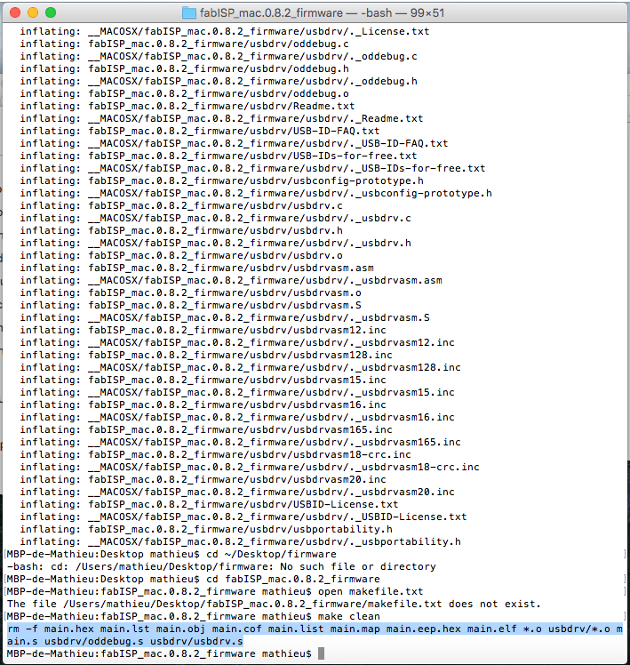
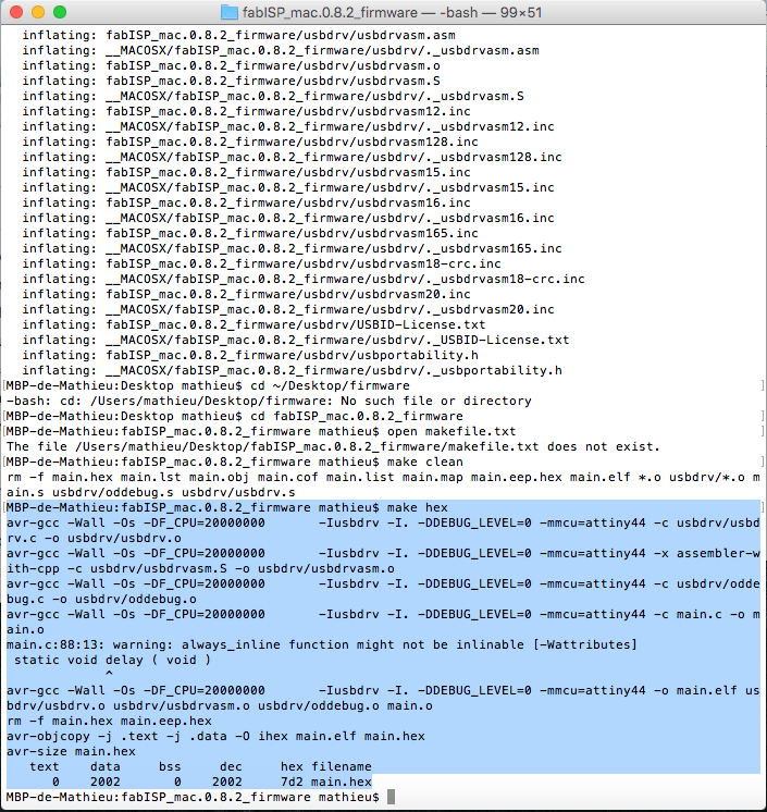
make hex
Finally let's connect our ISP into our usb socket and enter these command again in the firmware folder:
make fuse

make program
Now that your ISP is programmed I will prepare the Arduino IDE to be able to uplaud code using the FabISP.
Next I had to set-up my arduino IDE to be able to program via an attiny44, to do so, I followed this
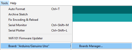
tutorial. First thing I had to do was to install the the Attiny support using the buit-in boards manager inside the Arduino IDE.
You need to go in the arduino preference and add an additional board manager URL: https://raw.githubusercontent.com/damellis/attiny/ide-1.6.x-boards-manager/package_damellis_attiny_index.json
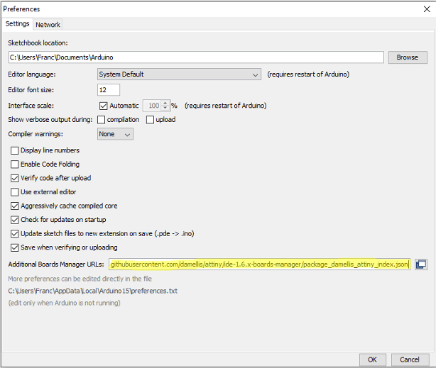
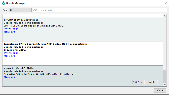
Once this is done, you can go into the board manager and install the Attiny support.
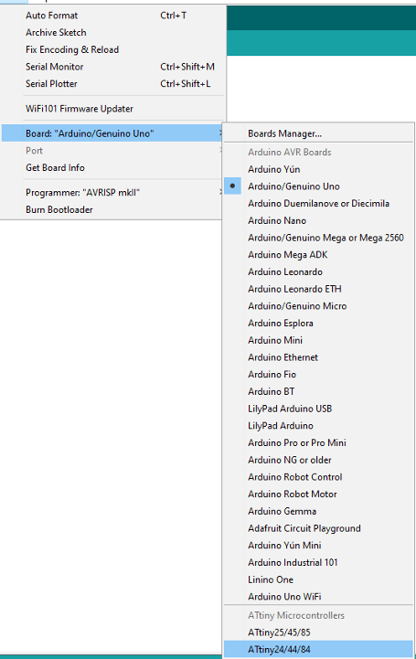
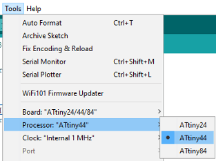
After that, you only need to go and setup your fabisp using these parameters, they are pretty straith forward.
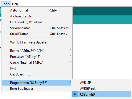
One thing that is important to know is that only a few arduino command are compatible with the Attiny's, here is a list of those command, you will have to find some work around to work with other command such as serial read and write.
                 pinMode()

                digitalWrite()

                digitalRead()

                analogRead()

                analogWrite()

                shiftOut()

                pulseIn()

                millis()

                micros()

                delay()

                delayMicroseconds()

                SoftwareSerial
![]()
It worked, my device is now shown as a USBtiny into my Device manager and I can uplaud code using the arduino IDE into other microcontrollers!